This page is wrote in English, but the researchs and builds are 100 % made in France !
(IA)
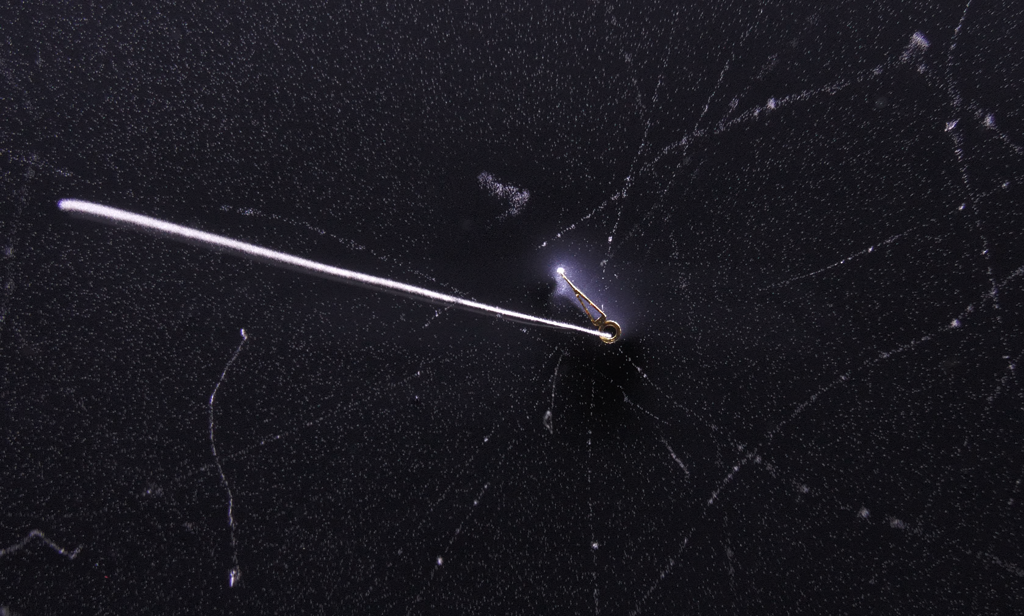
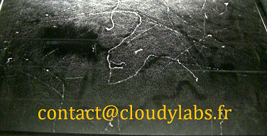
An alpha particle from a radium hands of an old radioactive watch
Choice of technology
A diffusion cloud chamber requires a cool source of about -30°C with a good coefficient of performance. There are 3 technologies that can achieve that : dry ice, thermoelectric cells or gaz compressors. This page compares the pros and cons of each of these technologies.
I don’t build thermoelectric cloud chambers anymore, a technology you can see in the ‘experiences page’ (I started them in 2010). With thermoelectric cells, it’s impossible to have an interaction surface bigger than 130 cm², unless you have a nuclear power plant to plug them. In the long term, I’m not convinced about their reliability because peltier cells need to be periodically replaced by new cells to keep good cooling performance as they undergo a lot of thermal stress. On the contrary, thermoelectric machines are very easy to build thus are perfect for Do It Yourself projects of few month of lifespan.
Now, I rather focus on cloud chambers cooled by a compressor (like a fridge). The building of a compressor-cooled cloud chamber is MUCH more complicated than doing a thermoelectric machine but it has some advantages : almost no maintenance, years of reliability (even a decade), any dimensions of surfaces can be reached and power consumption and price remain acceptable.
About the design of a compressor-cooled cloud chamber
There are a lot of designs possible which depend on how is used the machine. On the market one can find several ‘museum class’ compressor-cooled cloud chambers (Phywe for example). The looks are perfect and theses machines can run continuously through days. But they have big drawbacks : they are heavy, voluminous, thus impossible to move alone; they are costly (starting price about 35.000 euros) ; they are limited in their functions (difficulty to introduce specifics radioactive sources and unable to use magnetic fields to see the deviations of particles); they are slow to display particles in the first run (you need to wait about 20/30 min before observing something of interest due to inertia) and they use complicated or proprietary technology that prove costly to replace in case of failure (I had to repair one once and they asked 700 eur for a simple transformer…). I would add also that the quality of the signal could be more precise, but for public, they won’t notice that.
I’m not interested to be a competitor of ‘this market’. I’m focused in building ‘low cost machines’ with the best experience possible. ‘Low cost’ means that my designs will suffer from a lack of aesthetics : there will be some scratches from the construction, cable management would not be perfect, the cuts will not absolutely be straights ; so the overall construction will look a bit like ‘craftmanship’ (oh that solder could have been better…), … In a nutshell, I don’t attach much importance to the look, rather on the reliability of the machine.
For me, a cloud chamber remains a scientific experiment. It should have the 2 following features :
- As a machine : Simpler is better. The construction must be built with the minimum necessary while keeping the best quality of visualization of the particles.
- As a scientific experiment. To observe the interactions of particles it’s essential to use a magnetic field in the chamber. Also, the machine should allow the introduction of different radioactive sources inside.
1) Simpler is better
The machine should be built with the simplest materials without loosing the quality of the tracks displayed. A minimalist design results in a machine of low weight, easy to move around by a single person. One particular point is the design of the chamber, made of glass. In ‘museum class’ cloud chambers, there are always 2 glass containers. The first is the chamber surrounding the active surface and the second glass container encapsulates the first. The air space between the 2 glass container is heated to ~+30°C which prevents the formation of condensation along the walls of the primary glass container. A double glass chamber allows to use the machine in cold temperatures conditions and in non-stable temperature rooms. Thus, long operations can be reached with this design : the machine can run for days without being impacted by the environment.
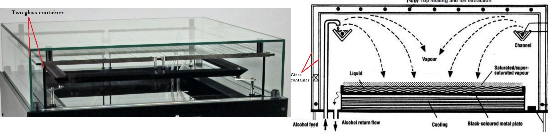
Schematic of a Phywe PJ45 cloud chamber, using 2 glass containers.
Unfortunately viewing through 2 layers of thick glass deteriorates the quality of observation. The observer is far from the interaction surface and there are losses of contrast from glass-absorption and parasitic reflections. Double glass enclosure add extra weight for the machine and it’s difficult to introduce radioactive sources inside the chamber because you have to cross 2 layers of glass.
Knowing this, I prefer using single-glass enclosure like all the physicists of the last century used to. But this implies that the top of the chamber has to be heated by an external thermal source. Indeed, the bottom of the chamber is at -35°C so the top glass of the chamber freeze over time resulting in the formation of condensation reducing the visibility. The condensation act like another source of evaporation of alcohol which perturb the equilibrium by inducing turbulences. So it’s important to not let this condensation form on the top glass. So the top surface has to be warmed by an external thermal source like an infrared lamp or a fan heater. If the top surface is heated, the machine can work several hours undisturbed. You can see that below with the machine working 11 hours :
Modern electronics are omnipresent in our world but I don’t trust them. I’m still impressed to see an old fridge working after 30 years and this is what I want to achieve when designing my cloud chambers. So my machines use basic electronics features, mechanical switches and theses components are easily replaceable at reasonable cost in case of failure. Reasonable means a few dozen euros, and easily means that you can buy these common components from any source like ebay or amazon, any time in the next 15 years and thus avoid any vendor-locking. Maybe it’s not a suitable business model to follow this days but I’m a scientific first not a commercial so you won’t find planned obsolescence here.
The Cloudylabs cloud chamber have the following electrical components :
- A cooling circuit. It provides an active surface cooled at about -30°C to -40°C. This circuit is designed to work for years without maintenance, it has the same components of an old fridge : a compressor, a filter drier, a condenser with fan and the evaporator (interaction surface). It’s possible to refill the system with refrigerant gas by any HVAC technician, as Schrader access valves are purposely presents for this.
- A standard DC power supply. It converts the main supply from 230V AC to 12VDC. The 12V feeds the LCD temperature controller, the led light, the pump and somes fans.
- A main switch 30 mA breaker to ON or OFF the machine. The 230V supply the compressor, the condenser’s fan, the DC power supply, the IR lamp, the high voltage circuit and a water heater.
- Two temperature controllers. They show the temperature of the active surface and the temperature inside the alcohol gutter tank in the chamber. The controller keeps the temperature to the desired value at any time thanks to a relay and a pump that heat or let cool the alcohol tank.
- A 12V led light bar to provide illumination in the chamber. Life expectancy is supposed to be a few thousand hours. Led bars are commonly sold for 4WD vehicles to provide additional outdoor lights and are quite heavy-duty.
- A high voltage circuit to provide about 2500 VDC in the top wire of the chamber, located above the alcohol gutter. If you ever happen to touch this circuit with your hands, you will feel a spike like an electrostatic discharge. « High voltage » here does not mean it is a danger to you, because the amperage is just a few microamps so the shock is identical to a mosquito electric racket. In normal use you can’t physically access the HV wires because they are inside the glass container.
The ruggedized, minimalist design ensures operational reliability in a wide range of field conditions, well beyond controlled laboratory environments. The unit remains fully functional after prolonged transport over rough terrain and is capable of performing accurate particle detection in austere settings—such as windy, dusty, or low-pressure environments where the particles belongs.
To validate this robustness, the prototype developed in April 2020, which serve as a « permanent crash test », has remained essentially unmodified—except for minor design tweaks—and has been deployed across France over several years, conducting field demonstrations in both urban centers and remote areas :
2) A scientific experiment
The machine should allow the use of magnetic fields to observe the deflection of light particles (electrons, positons, slow muons). A magnetic field allows to discriminate between positive and negative particles just by looking at their direction of deviation. The magnetic field B is created by a NdFeB magnet put under the active surface. The intensity of magnetic field in the chamber is about 50 to 100 mT. By measuring the angle of curvature of a particle, you can also estimate it’s energy (a good practical exercise for students !).
The machine should be designed to put radioactive sources in the chamber. The are 3 holes in the glass chamber to put easily these sources inside.
To summarize
The system delivers exceptionally thin, high-contrast particle tracks for unmatched visual clarity. (One of our clients noted that our tracks are twice as sharp as those produced by competing machines).
- Unmatched Viewing Comfort: The single-layer glass design completely eliminates the double reflections and distortion typical of dual-enclosure systems.
- Highly Portable: Weighing only 36 kg, the unit is easily carried by a single person from one classroom to another.
- Engineered for Durability: It can safely be transported in a car trunk over thousands of kilometers and remain fully operational upon arrival.
- Simple & Reliable: No complicated maintenance, proprietary parts, or over-engineered electronics. Ready in just 12 minutes after power-up to start viewing particle tracks.
- Cost-Effective: Need to replace a part? Components can be swapped out easily at any time at minimal cost.
- Magnetic Deflection: You can use a magnetic field to deflect particles using 25 mm thick magnets up to 200 x 130 mm.
The technical considerations & limitations :
- Requires an external infrared lamp, which takes up some space (caution: hot surface during operation).
- Runs continuously for 3 to 4 hours before requiring an alcohol refill (the machine does not need to be turned off for refilling).
- Not recommended for use in room temperatures exceeding 35°C (extreme summer conditions). It still works, but I don’t like to see my compressor suffer.
- Requires methanol to achieve this level of track quality. Methanol is toxic if ingested and must be handled with appropriate care.
Test at 34°C outside
Garage-Built, Professional Quality
Historically, many great scientific tools started in small workshops =)
Every unit is hand-built and rigorously tested by myself, an independent engineer, in my garage workshop. I am not a massive corporation, and my design is industrial and functional—but I never compromise on performance, safety, and reliability.
This is the result of 15 years of continuous research, tweaking, and field testing—and my research is still ongoing.
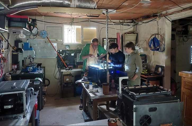
A renowned astronomer from l’observatoire de Paris and scientists from La Sorbonne visiting my workshop in summer 2026 to observe the particle tracks
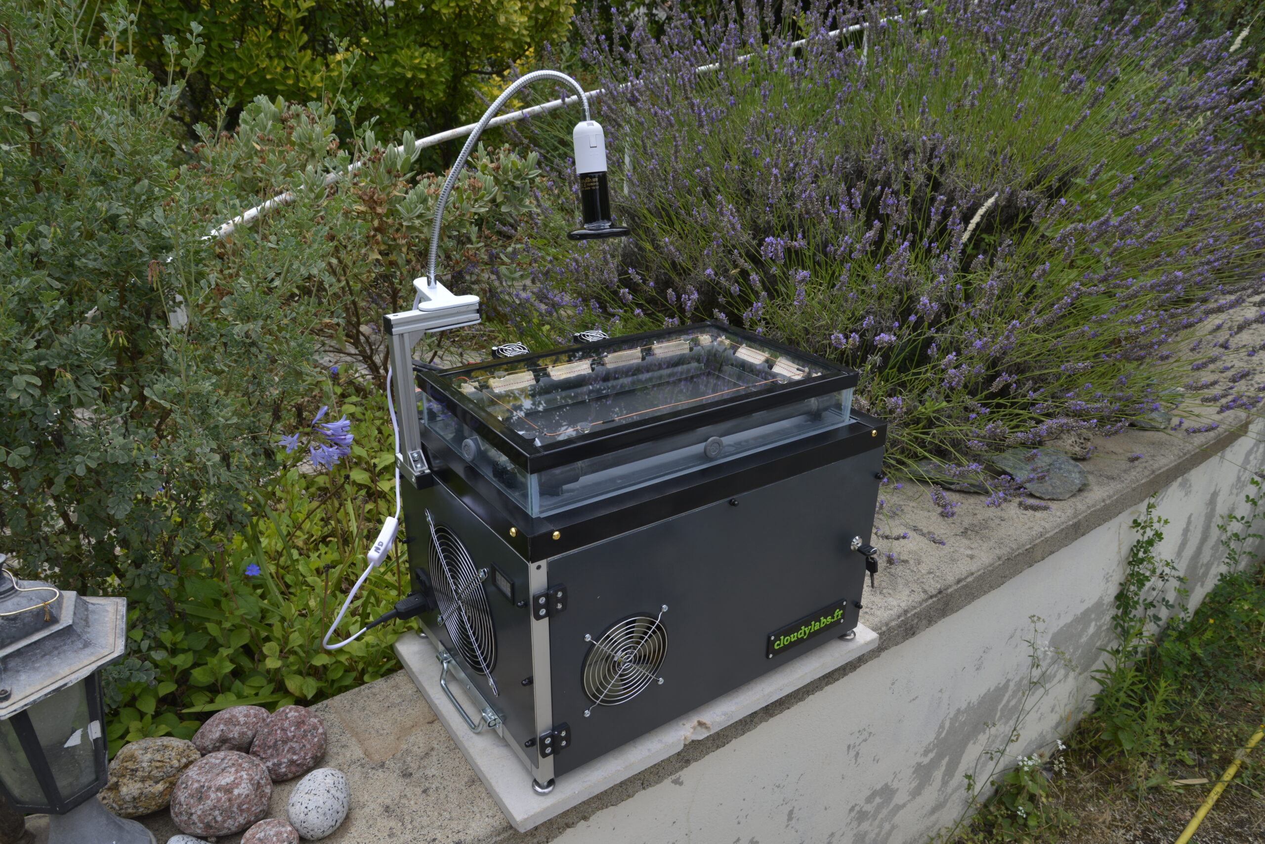
photo of the machine of 2024, the 2026 version show only minor upgrades
Engineering note : For a 110VAC version (USA country), I need to build a specific one and invest in heavy hardware. I can’t use simply a step-up transformer 230VAC to 115VAC and feed the machine with, because 115VAC country output 60 Hz and the compressor is designed to work at 50 Hz. This imply that the compressor will run at 60Hz and thus will turn 20% faster, reducing its life expectancy. So a machine working on a power grid at 60 Hz should use components designed to work at 60 Hz. To build a reliable machine working at 110VAC@60Hz living in a country where it’s 230VAC@50Hz (here in France), I need a powerful frequency converter. I started researchs at the beginning of 2026 to make such machine. It should be finish at the end of this year! => I received my 10 kVA frequency converter this summer ! If you are interested in a 115V US version, let me know.
If you are interested to get such cloud chamber you can contact me below but please note that the building time is important so I can’t respond to hurry requests.
Please don’t ask me how to build your own cloud chamber, as I don’t have much time to help everyone and there is enough information on internet to make your own. I hope you will understand that I’ve spent so much time to have something workable so I can’t give you all the secrets of the internal working of the machine. Thanks for your interest.
Range of price for France : 9500 euro tax and shipping included.
Machines sold and running ! : https://www.cloudylabs.fr/wp/references/
Safety note for whom who like to reproduce this machine :
To be honest building phase change machine is just…dangerous. Remember that you work with flammable liquid & gas, high temperature to solder (800°C) electrics fields and many other toxic components (specially when I make the evaporator) so set up all this things into a safe machine is not so easy to master, be careful ! If you want to build a cloud chamber at reasonable cost, the thermoelectric coolers are a solution to begin with (for example you can download a guide here). It’s nice to see something which work, but don’t underestimate the harsh way it needed to make it usable.